
Page 43 - USI Newsletter No.94
P. 43
Intelligence 資訊特快車
Express NO.94
System Power Management Grouped Addressing
I3C provides a mechanism for master to inform slave what behavior is expected subsequently. I3C defines 4 According to different function and purpose, target device can be divided into different groups. I3C can assign an
states. States have both a broadcast version and a directed version. Target device can use received activity state address to the group. So master can broadcast messages to the group. Target device will store the group address
hint to adjust internal setting, which can realize the power saving. together with its dynamic address. By the way, same device can have many different group addresses. But
interrupt cannot use group address to initiate.
Table 1 Activity States
Activity State Activity Interval CCC Multiple Master
0 1μs ENTAS0
1 100μs ENTAS1 I3C bus support multiple masters, but only one master is active on line at the same time. So there is active master
2 2ms ENTAS2 and secondary master definition. The controller role can be transferred by using hand-off procedure. Either one
3 50ms ENTAS3 controller-capable device can directly the flow of passing the role back and forth, or else secondary controller
can request the controller role from the active controller.
Another way, by using hot-join method, target device can be shut down when it is not required for a while.
Moreover, I3C target device can also enter sleep modes to achieve power saving. Multi-Lane Communication
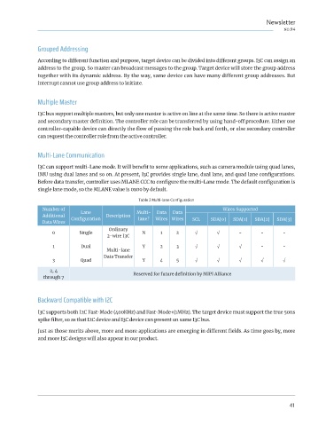
I3C can support multi-Lane mode. It will benefit to some applications, such as camera module using quad lanes,
Dynamic Address Assignment IMU using dual lanes and so on. At present, I3C provides single lane, dual lane, and quad lane configurations.
Before data transfer, controller uses MLANE CCC to configure the multi-Lane mode. The default configuration is
In the process of initialization, each I3C target device will get a unique dynamic address. In system, master uses
concatenated 48bit Provisioned ID, BCR and DCR to set priority and complete the address assignment in order. single lane mode, so the MLANE value is 0x00 by default.
Table 2 Multi-lane Configuration
Number of Lane Multi- Data Data Wires Supported
Additional Description
Data Wires Configuration lane? Wires Wires SCL SDA[0] SDA[1] SDA[2] SDA[3]
Ordinary
0 Single N 1 2 √ √ - - -
2-wire I3C
1 Dual Y 2 3 √ √ √ - -
Multi-lane
Data Transfer
3 Quad Y 4 5 √ √ √ √ √
2, 4
through 7 Reserved for future definition by MIPI Alliance
Backward Compatible with I2C
I3C supports both I2C Fast-Mode (400KHz) and Fast-Mode+(1MHz). The target device must support the true 50ns
spike filter, so as that I2C device and I3C device can present on same I3C bus.
Just as those merits above, more and more applications are emerging in different fields. As time goes by, more
and more I3C designs will also appear in our product.
Fig 5 Dynamic Address Assignment
40 41