
USI Blog
Top trending topic for the latest innovation technology, application and industry insight.
Search
- 10/16/2026
From Untestable to Precisely Tested: Cracking the High-Density ICT Challenge
Author: Anson Liu, Senior Manager | Test Engineering Department (TED)
Before a circuit board can ship, it must pass round after round of electrical testing. Yet for test engineers, the biggest headache has never been catching bad boards. It is boards that simply cannot be tested. When a customer covers every test pad (the contact point where a probe lands) with green solder mask to improve noise immunity, conventional testing is effectively blinded: with nowhere for probes to land, test coverage collapses to about 30%.
At USI, we have long regarded test engineering as the last line of defense for quality. The ultimate goal of test engineering is "test yield," which is also considered a key indicator of a company's manufacturing competitiveness. This article explains how USI test engineering team used a combination of soft compression, vision alignment and robotics to bring ICT (In-Circuit Test) coverage back above 90% on boards with no test points, push test yield to 95%+, and cut per-board test time from 23 seconds to under 5.
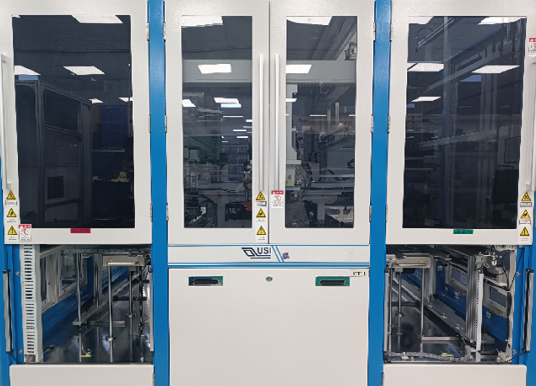
Figure 1 | ICT automated test equipment in stable mass production: a robotic arm replaces manual loading and unloading, CCD vision handles alignment, and one operator can tend two machines.
Where the Trouble Starts: A Board with No Test Points
First, the problem. For noise-immunity reasons, the customer's X/B models use a layout in which the pads are covered by solder mask, leaving almost no test points that probes can reach. ICT works by pressing probes onto test points one by one to measure electrical characteristics. No test points, no test. This is the ceiling ICT is hitting industry-wide as routing density rises and features keep shrinking.
To break through, USI tried two approaches, each with a critical flaw:
- Conductive foam testing: Conductive foam replaces probes with indirect contact, and the process is simple. But the testable area is too small, so coverage reaches only about 30%. The foam also wears and picks up contamination easily, driving up the false-call (NDF, No Defect Found) rate. Mass-producing this way would carry significant quality risk for downstream shipments.
- FPC gold-finger compression (manual): A board-to-board approach that mimics the customer's bonding process "borrows" the test points through the gold fingers, lifting coverage to 90%+ in one step. The problem was alignment. The spacing between gold-finger pins is only 0.165mm, pin width is 0.25mm, and the alignment spec is as tight as ±0.05mm. With alignment done entirely by eye, the slightest offset caused false calls, operators tired quickly, and test yield hovered around 75%. That was not enough to support mass production.
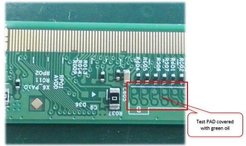
Figure 2 | Test pads on the PCBA are covered by green solder mask, leaving probes nothing to contact. This is where the whole challenge begins.
USI's Solution: Let Machines Take Over the Hardest Step, Alignment
The logic is straightforward. FPC gold-finger compression already delivers strong coverage; what really held it back was manual alignment. So stop asking people to do what machines do better. The ICT automation solution developed by the USI team keeps the high coverage of FPC gold-finger compression and uses CCD vision alignment, a toggle-latch fixture and a robotic arm to free operators from alignment and handling.
So how do gold fingers become test points? The FPC is pressed down through a soft elastomer surface, so it does not damage the contacts when compressed onto the product's gold fingers, and every gold-finger pin can serve as an independent test point. This maximizes probe access in a single step, which naturally lifts coverage. And because the test is non-destructive, it is gentler on the product.
How do you hand ±0.05mm alignment over to a machine? That is the technical crux of the entire solution. A CCD (Charge-Coupled Device) vision camera captures the positions of the PCBA and FPC gold fingers in real time, and the system makes fine motor adjustments to compensate automatically, keeping every compression within ±0.05mm. Human eyes tire and hands shake; a CCD camera does not. Precision and consistency are achieved at the same time.
The board under test is locked in place automatically by a toggle-latch fixture, while the robotic arm handles loading, transfer to test, unloading and pass/NG sorting, so no operator has to handle boards one by one. One person can tend two machines, cutting staffing in half.
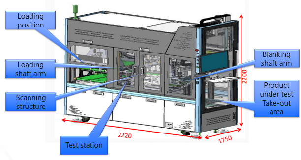
Figure 3 | The ICT automated test equipment has three stations (loading, testing and unloading), linked by a robotic arm into a fully automated flow
Settling Three Accounts at Once: Test More, Test Right, Test Faster
Whether automation is worth the investment ultimately has to be proven on the books. Put the key metrics from before and after deployment side by side, and the change comes down to three points: more can be tested, more is tested correctly, and testing finishes faster.
| Metric | Before (manual compression / conventional) | After (ICT automation) |
|---|---|---|
| Test coverage | Conductive foam ~30%; manual compression 90%+ | 90%+ |
| Test yield | Manual alignment ~75% | 95%+ |
| Per-board test time | 23.1 sec | 4.9 sec (18.2 sec saved per board) |
| Units per hour (UPH) | 156 (1 operator, 1 machine) | 735 (1 operator, 2 machines) |
| Test machines required | 2 | 1 |
The first two rows are the quality account. Coverage holds firmly above 90%, and test yield climbs from 75% under manual operation to 95%+, all but closing the gaps once left by missed tests and false calls. The last three rows are the efficiency account. Per-board test time drops from 23.1 to 4.9 seconds, two machines are consolidated into one with one operator tending two machines, and hourly output per machine (UPH) jumps from 156 to 735. Notably, these gains are not trade-offs pulling against each other; they all moved in the right direction at once.
Holding the 0.05mm Line: Machines Don't Fade in the Eighth Hour
Whether this solution could reach mass production hinged on a very practical issue. With gold-finger spacing of just 0.165mm, any misalignment beyond ±0.05mm can trigger a false call, and that level of precision is hard for human hands and eyes to sustain over a full shift. Even the most experienced technician's eyes blur, hands shake, and work slips by the eighth hour.
Our approach is to never let the system "trust" any single setup. As each board arrives, the CCD camera first measures the actual position of the gold fingers; the controller calculates the offset in real time and drives the motor to fine-tune the FPC position before pressing down. Placement, alignment, press-down and compression testing are tightly linked, with realignment in every cycle rather than a fixture that is "calibrated once and used forever." Because every board is recalibrated, alignment stays within spec even at such a fine pitch. Accuracy no longer depends on who is on shift or how many boards have been run.
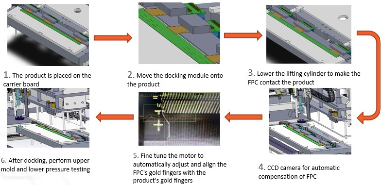
Figure 4 | CCD automatic compensation and precision calibration flow: placement → alignment → press-down → compression test, with automatic recalibration in every cycle
Labor and Time Saved Become Our Customers' Competitive Edge
Beyond the technical metrics, the real value of this achievement is that it drives down quality risk and mass-production cost at the same time, giving customers greater flexibility in design and supply:
- Stronger quality assurance: Even with high-noise-immunity designs that have no test points, coverage stays at 90%+ and test yield at 95%+, stopping defects before they ship.
- Lower test cost: Machines cut from two to one, one operator per two machines, and per-board test time reduced by nearly 80%, improving the entire test cost structure after deployment.
- Faster production ramp: UPH rises from 156 to 735, more than doubling capacity and giving delivery commitments a firmer footing.
*Figures in this article are engineering reference values and mass-production results; actual specifications depend on project design.
Frequently Asked Questions (Q&A)
Q: What is ICT (In-Circuit Test), and why does it fail when there are no test points?
A: ICT (In-Circuit Test) uses probes that contact test points on a circuit board to measure the electrical characteristics of components and traces one by one. When a customer covers the test pads (PAD) with green solder mask for noise immunity, there is nowhere for probes to land, so conventional ICT coverage plunges to about 30% and quality risk rises sharply.
Q: What is USI's VP ICT Automatic Test, and how does it differ from conventional ICT?
A: It is a fully automated ICT solution developed in-house at USI's Huizhou site, combining FPC gold-finger compression, CCD vision alignment, a toggle-latch fixture and robotic loading and unloading. Unlike conventional probe-based or manual compression testing, it tests boards without test points automatically, accurately and efficiently, achieving 90%+ coverage and 95%+ test yield.
Q: How does FPC gold-finger compression testing work, and can it damage the product?
A: It uses a board-to-board approach that mimics the customer's bonding process. The soft elastomer surface of the flexible printed circuit (FPC) is pressed onto the product's gold fingers, turning each gold-finger pin into an independent test point. Because contact is made through a soft elastomer, the test is non-destructive and does not scratch the gold fingers, balancing coverage with reliability.
Q: What role does CCD vision alignment play, and how accurate is it?
A: A CCD (Charge-Coupled Device) camera captures the gold-finger positions in real time, and the system drives motors to compensate automatically, consistently holding FPC-to-PCBA alignment within ±0.05mm. This real-time closed-loop calibration is what enables stable mass production even with gold fingers at a fine 0.165mm spacing.
Q: How much did efficiency and test yield improve after ICT automation?
A: Test coverage remains at 90%+, and test yield rose from 75% under manual operation to 95%+. Per-board test time fell from 23.1 to 4.9 seconds (18.2 seconds saved per board), units per hour (UPH) rose from 156 to 735, and the number of test machines was reduced from two to one.
Q: Why automate instead of continuing with manual FPC compression?
A: Manual FPC compression does achieve 90%+ coverage, but ±0.05mm alignment depends entirely on the naked eye. Operators tire easily, test yield is only about 75%, and with one operator per machine and long cycle times, it cannot sustain mass production. Automation hands the hardest tasks, alignment and handling, to CCD vision and robotic arms, solving test yield, labor and efficiency at the same time.
Q: What value does this technology bring to USI's customers?
A: Even with high-noise-immunity designs that have no test points, customers can maintain high coverage and test yield, stopping quality risks before shipment, while benefiting from lower test costs (half the machines, one operator per two machines) and higher throughput (UPH more than doubled). USI thus moves beyond pure manufacturing to become an integration partner that helps customers put production test solutions into practice.
Search
Recent Articles
-
From Untestable to Precisely Tested: Cracking the High-Density ICT Challenge
 From Untestable to Precisely Tested: Cracking the High-Density ICT Challenge
10/16/2026
From Untestable to Precisely Tested: Cracking the High-Density ICT Challenge
10/16/2026
-
Inside 1.6T Optical Transceivers: How Optical Simulation and Coupling Shape Performance and Yield
 Inside 1.6T Optical Transceivers: How Optical Simulation and Coupling Shape Performance and Yield
09/21/2026
Inside 1.6T Optical Transceivers: How Optical Simulation and Coupling Shape Performance and Yield
09/21/2026
-
The Next Frontier in AI Computing: Design and Manufacturing of 1.6T Optical Transceiver Modules
 The Next Frontier in AI Computing: Design and Manufacturing of 1.6T Optical Transceiver Modules
09/07/2026
The Next Frontier in AI Computing: Design and Manufacturing of 1.6T Optical Transceiver Modules
09/07/2026
-
A Key Step in Further Wearable Miniaturization: Selective Encapsulation with Fence + VPE
 A Key Step in Further Wearable Miniaturization: Selective Encapsulation with Fence + VPE
08/17/2026
A Key Step in Further Wearable Miniaturization: Selective Encapsulation with Fence + VPE
08/17/2026
-
Enabling AI at Scale: The Rise of Silicon Photonics and Optical Transceiver
 Enabling AI at Scale: The Rise of Silicon Photonics and Optical Transceiver
08/03/2026
Enabling AI at Scale: The Rise of Silicon Photonics and Optical Transceiver
08/03/2026
-
When AI Learns to “Read”: Using Deep Learning to Tame the False-Alarm Storm on SMT Production Lines
 When AI Learns to “Read”: Using Deep Learning to Tame the False-Alarm Storm on SMT Production Lines
07/13/2026
When AI Learns to “Read”: Using Deep Learning to Tame the False-Alarm Storm on SMT Production Lines
07/13/2026
-
Catching Invisible “Micro-Failures”: Safeguarding SiP Reliability Testing with Daisy Chains
 Catching Invisible “Micro-Failures”: Safeguarding SiP Reliability Testing with Daisy Chains
06/29/2026
Catching Invisible “Micro-Failures”: Safeguarding SiP Reliability Testing with Daisy Chains
06/29/2026
-
The Hidden Rival Inside an EV’s Heart: Cracking the Power-Loss Puzzle with “Physical Modeling”
 The Hidden Rival Inside an EV’s Heart: Cracking the Power-Loss Puzzle with “Physical Modeling”
06/17/2026
The Hidden Rival Inside an EV’s Heart: Cracking the Power-Loss Puzzle with “Physical Modeling”
06/17/2026
-
Behind the MFG. | From "Manufacturing" to "Creation" Ep.2: Innovation Built from Zero to One
 Behind the MFG. | From "Manufacturing" to "Creation" Ep.2: Innovation Built from Zero to One
05/28/2026
Behind the MFG. | From "Manufacturing" to "Creation" Ep.2: Innovation Built from Zero to One
05/28/2026
-
Behind the MFG. | From "Manufacturing" to "Creation" Ep.1: Unveiling USI’s Technological Vanguard
 Behind the MFG. | From "Manufacturing" to "Creation" Ep.1: Unveiling USI’s Technological Vanguard
05/07/2026
Behind the MFG. | From "Manufacturing" to "Creation" Ep.1: Unveiling USI’s Technological Vanguard
05/07/2026
Keep up with top trending topic
For the latest innovation technology, application
and industry insight.
Subscribe Our Blog
For the latest innovation technology, application
and industry insight.